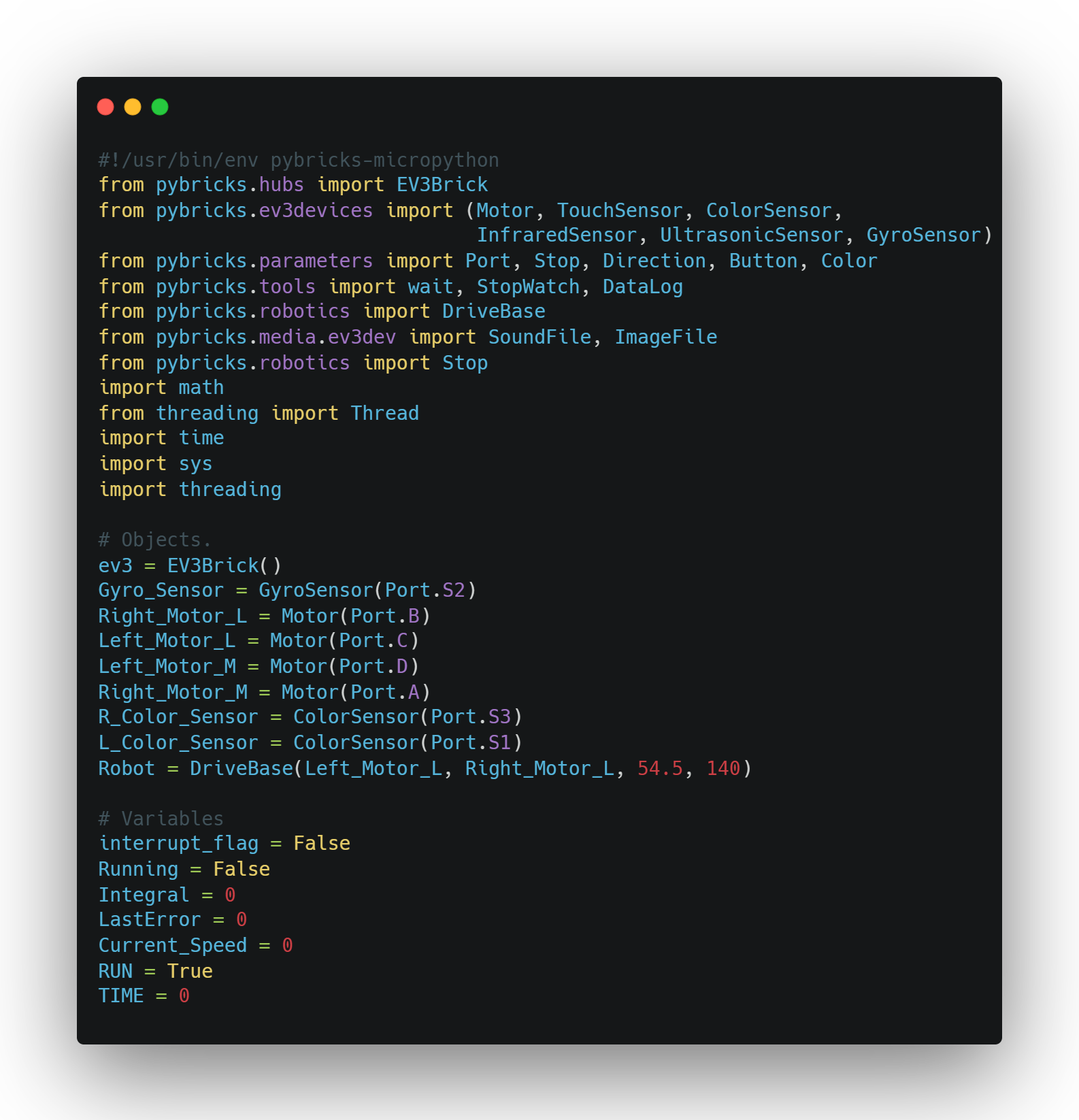
This MicroPython script is designed to control a LEGO EV3 robot using the Pybricks library. It begins by importing essential modules for hardware control, such as motors, sensors (gyro and color), and system tools like math and threading. The EV3 brick and multiple motors are initialized, likely with two dedicated to movement (Left_Motor_L and Right_Motor_L) and two possibly for attachments or mechanisms (Left_Motor_M and Right_Motor_M). Two color sensors are set up for detecting colors or following lines, while a gyro sensor is used to measure rotation or orientation. The robot’s drive base is configured with the wheel diameter and axle track for precise movement. Additionally, variables related to robot state and motion control, such as interrupt_flag, Running, and PID-related terms (Integral, LastError, Current_Speed), are declared—indicating that the robot may use PID control for navigation or line following. The script sets up the foundation for a responsive and sensor-driven robotic system, with support for multi-threading to handle complex tasks.
The functions Robot_Break, Move_Tank, Gyro_Check, and Motor_Check work together to enable precise control and movement of the robot in different scenarios. Robot_Break is a simple function that stops both left and right motors using the brake mode, ensuring the robot halts immediately. Move_Tank sends speed commands to the left and right motors, effectively controlling the robot’s movement in a tank drive style, where individual motor speeds are set for turning or straight motion. Gyro_Check uses the gyro sensor to rotate the robot to a specific target angle by applying proportional speed adjustments to the motors, moving the robot in one direction until the target is reached and then adjusting as needed. If the interrupt_flag is set, it breaks the loop and stops the robot. Similarly, Motor_Check is used to move the robot a specific distance by continuously adjusting motor speeds until the target distance is achieved, checking if the robot has reached the desired position or if an interrupt occurs. Both Gyro_Check and Motor_Check utilize Move_Tank to control motor speeds in response to the sensor feedback, while also ensuring the robot halts at the end with Robot_Break. Together, these functions allow the robot to navigate accurately by combining basic motor control with sensor feedback and interruption handling.
This function, PID_WALK, builds on the previously defined hardware setup and variables by providing a reusable way to implement PID (Proportional-Integral-Derivative) control logic for robot movement. It takes in parameters for speed (Speed), a target angle (TA), and the three PID constants (KP, KI, KD) to dynamically adjust how the robot corrects its course. The function calculates the error as the difference between the desired angle and the current angle from the gyro sensor. It then computes the proportional, integral, and derivative terms based on that error. These terms are weighted by their respective constants and summed to produce a Steering value, which is passed into the Robot.drive() function along with the speed to move the robot while continuously adjusting its direction. The LastError is updated each time to keep track of changes in error over time, which is essential for calculating the derivative. This function ties into the earlier code by utilizing the global Integral and LastError variables and the initialized gyro sensor and drive base, allowing other parts of the program to easily implement smooth and accurate turns or straight-line correction using PID logic.
The Speed_Control function complements the previously defined PID_WALK method by dynamically adjusting the robot's movement speed, making it smoother and more adaptable based on the situation. It uses a gradual acceleration or deceleration approach depending on the desired behavior. The function takes in a target speed (Speed), an acceleration constant (KA), a boolean flag for deceleration (Decceleration), and a deceleration factor (DF). It starts by calculating a small increment (Initial_Speed) based on the acceleration constant. If the robot is still accelerating (Decceleration is False) and hasn’t yet reached the desired speed, it increases Current_Speed gradually. If deceleration is requested, it reduces the speed more aggressively using the deceleration factor and ensures that the speed doesn’t drop below a minimum threshold of ±50, which helps prevent the robot from stalling. If neither condition applies, it sets the speed directly. The function then returns the updated speed value, which is intended to be used as the Speed parameter in the PID_WALK function. It ties seamlessly with the earlier code by manipulating the global Current_Speed variable and allowing the robot to start, stop, and change speeds smoothly, enhancing the effectiveness and realism of the PID-controlled walking system.
The PID function ties together the previously defined Speed_Control and PID_WALK functions, creating a comprehensive control system for the robot to walk with smooth, accurate, and responsive movement using PID control. It takes several parameters: target speed (Speed), target angle (TA), total distance (TD), and the three PID constants (KP, KI, KD), along with an acceleration constant (KA), a deceleration factor (DF), and an optional boolean flag (doMcheck) for a motor check after completing the walk. Initially, it resets the motor angles and adjusts the target distance (TD) based on the sign of the speed to ensure proper movement direction. The function then enters a loop, continuously adjusting the robot’s movement until it covers the specified distance (TD). During the loop, the robot’s deceleration phase is triggered when it’s close to the target distance, and the speed is adjusted accordingly using the Speed_Control function. It checks for interruptions via the interrupt_flag, stopping the robot with a brake if necessary. The PID_WALK function is called in each loop iteration, using the adjusted speed and PID parameters to fine-tune the robot’s movement, ensuring precise path correction. Once the target distance is reached, the robot stops, and if doMcheck is enabled, a motor check is performed to verify proper motor function. The final step clears the EV3 screen and displays the robot's traveled distance. This function provides a nearly flawless walking behavior by combining real-time speed control with PID steering and smooth deceleration. It integrates with the previously set up hardware, control flags, and sensors, enabling the robot to walk with minimal errors in direction and speed.
The PID_COLOR_R function is a variation of the previous PID function, but instead of stopping based on the distance traveled, it stops using feedback from the right color sensor (R_Color_Sensor). This allows the robot to halt precisely when it detects a specific surface reflection, making it useful for line-following tasks or responding to marked zones on the field. The function takes in parameters similar to the standard PID walk: speed (Speed), target angle (TA), target reflection value (TC), a tolerance range (Margin), PID constants (KP, KI, KD), and an acceleration constant (KA). It begins by resetting the angles of the left and right motors to ensure consistent movement tracking. The main loop continues running until the right color sensor detects a reflection value within the specified margin of the target reflection value, essentially waiting until the robot "sees" the correct surface condition. Inside the loop, it checks for an interrupt_flag to immediately stop the robot if needed. The function then calls PID_WALK, using the output of Speed_Control to adjust the robot’s speed on the fly, while keeping its direction stable with PID logic. Once the desired surface condition is detected, the robot stops using a brake. This version integrates seamlessly with the earlier setup and leverages the existing PID and speed control logic but replaces distance-based stopping with a sensor-based trigger, making it ideal for color-sensitive navigation or event-driven stopping scenarios.
The PID_TIME and CHECK_TIME functions work together to create a time-based variant of the previously described PID walking system, where the robot stops moving after a specified duration instead of relying on motor angle, distance, or sensor input. The PID_TIME function initiates by resetting the motor encoders for consistent tracking, then sets a global RUN flag to True and stores the desired time in the TIME variable. It spawns a separate thread to execute the CHECK_TIME function, which waits for the specified time duration using the wait() method and then sets RUN to False, signaling the robot to stop. While RUN remains True, the function enters a loop where it continuously checks for an interrupt and uses the combined Speed_Control and PID_WALK functions to drive the robot at the appropriate speed and direction, maintaining smooth motion through PID control. Once the time elapses and RUN is set to False, the robot stops using a brake, clears the EV3 screen, and prints the distance it traveled during the timed run. This approach is particularly useful for scenarios requiring timed movement without relying on environmental feedback, offering a flexible and autonomous control strategy that ties directly into the previously defined motion infrastructure using global control flags, threading, and real-time PID adjustments.
The P_Gyro_Turn function operates independently from the previously described PID-based movement functions and is specifically designed to perform highly accurate turns using a proportional control strategy. It aims to rotate the robot to a specified target angle (Target) using the gyro sensor for real-time feedback. The function takes in proportional gain values for the left and right motors (LP and RP), as well as optional parameters for minimum and maximum motor speeds to ensure stable performance without overshooting or stalling. Inside a loop, it continuously checks the current angle against the target. If an interrupt_flag is triggered, the robot stops immediately using brake mode, and a fourth color sensor on port S4 is initialized, possibly for future use in obstacle detection or color-based decisions. The proportional error is calculated as the difference between the current and target angles, and it is multiplied by the gain values to compute the speed for each motor. These speeds are then clamped within the defined minimum and maximum range while preserving their direction. The Move_Tank function is called to apply these speeds, and a short delay is used to prevent overwhelming the CPU. Once the robot reaches the desired angle, the loop ends, the robot is stopped cleanly using Robot_Break(), and a final Gyro_Check(Target) call likely verifies or recalibrates the final position. This function provides a precise, real-time turning method based solely on proportional control, making it ideal for sharp, accurate pivots when full PID isn’t necessary or would be too complex.